Appearance
Connections & Wiring
A cable connects an output to an input. Some cables carry the sound you hear; others carry notes or values that control that sound. The pin's name, direction and signal type tell you where to connect it.
This guide uses the Saw, Filter, Volume and Brightness knob from Your first patch. Start there if you have not made a sound yet. Here, you will learn to draw and remove a cable, choose a signal type, and send one output to several destinations.
Make your first connection
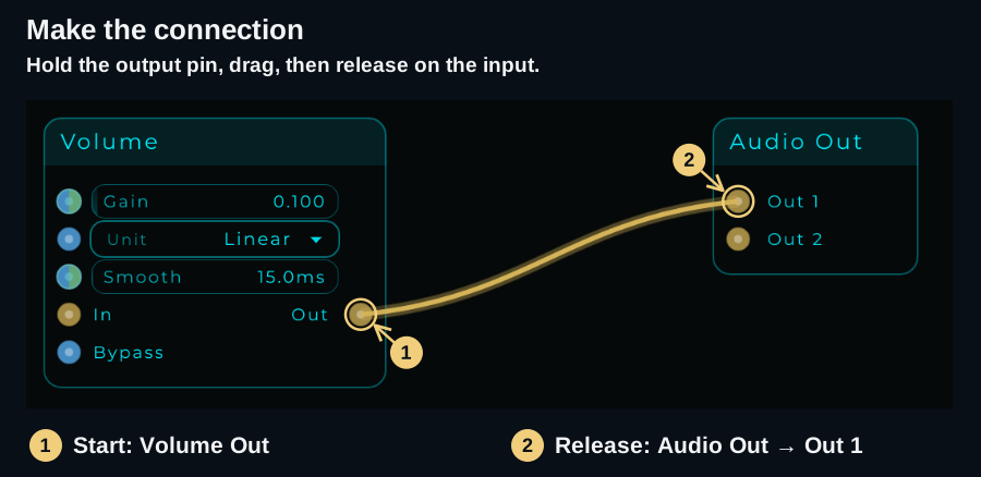
Take Volume → Audio Out as an example. The small circles on the node are its pins. Volume's Out pin is on the right; Audio Out's Out 1 and Out 2 pins are on the left. Despite their names, these are inputs to the Audio Out node: they feed your first and second output channels.
- Press and hold the Volume Out pin.
- Drag the cable to Audio Out → Out 1. Compatible pins are highlighted as you drag. Aim at the circle, rather than the node's title or its body.
- Release on the pin to connect it. A thin collar around a connected pin shows that it is in use.
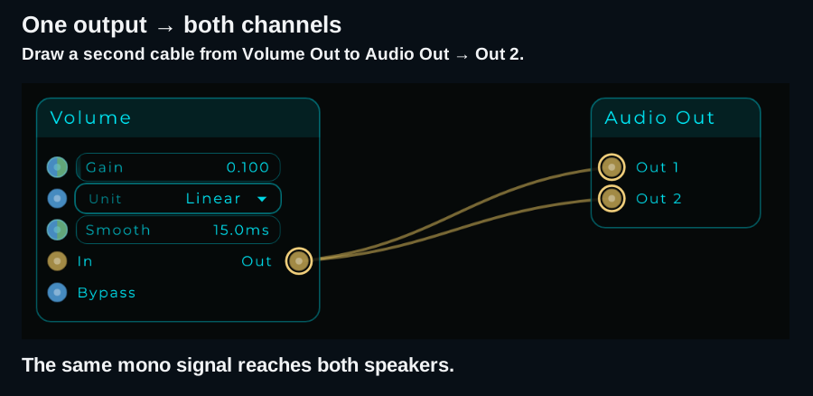
To send this mono signal to both speakers, repeat from the same Volume Out pin to Audio Out → Out 2. You now have two cables leaving one output.
Choose the signal you need
These are the pin colours in the Default theme. Custom looks may use different colours, so check the pin's name too.
| Type | What travels through it | A practical connection |
|---|---|---|
 Audio Audio | The sound itself, as a continuous signal | Saw Out → Filter In L |
 Data Data | Individual values or events: numbers, text, button presses and more | Brightness Out → Filter Freq |
 CV CV | A continuous control signal for modulation | LFO Out → Filter Freq |
 MIDI MIDI | Note messages, velocity, CC, pitch bend and other MIDI messages | MIDI In → MIDI To CV, to extract pitch and gate |
Audio is what you hear. Data and CV tell another node what to do. MIDI describes a performance. A MIDI cable carries note messages, so it needs an instrument or a conversion stage before it can produce sound. See MIDI.
The same filter, controlled two ways
Keep the audio path unchanged:
Saw → Filter → Volume → Audio Out
The following images show just the control connection to Filter Freq. The downloadable patches also contain the complete audio path. Both make a continuous tone without MIDI; start with your listening volume low and set Volume Gain = 0 to silence them.
Turn a knob: Data
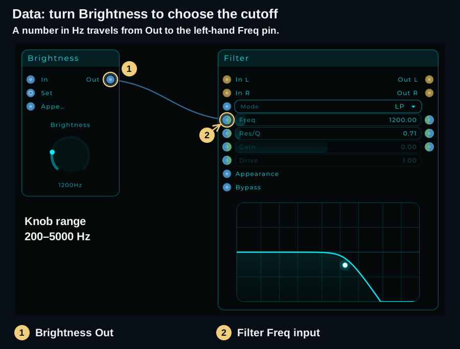
Connect Brightness Out to the input on the left of Filter's Freq row. Moving the knob sends a new frequency to the filter. Leaving it alone leaves the cutoff at that value.
Let a node move it: CV
Disconnect the Brightness cable, then connect LFO Out → Filter Freq. Use Out, which carries the LFO's value, rather than Phase Out. The LFO now moves the cutoff automatically.
For this example, set the LFO to Free (Hz), Internal transport, Sine, Freq 0.5 Hz, Min 300 and Max 4000. Use its Play control if it is paused or stopped. One cycle takes two seconds.
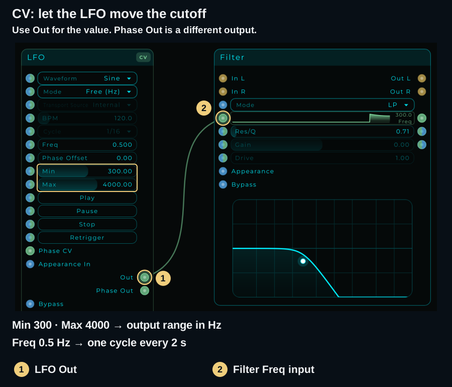
Check the range, not just the cable. A default LFO range of 0–1 is too small to be useful as a cutoff in Hz. Set its Min and Max as above, or use Map to translate a modulation range into the units the destination needs.
Events and streams
Data is event-based. A message arrives when a node sends it. A knob typically sends a value when you change it; a trigger can send another event even if it carries the same value. Data is not a continuous audio-rate signal.
CV modulation runs as a stream, processed sample by sample. Even a slow LFO can provide a continuous signal. “Slow” describes how quickly its waveform moves, not whether the connection is Data or CV. A square-wave CV signal can still jump abruptly: CV describes the way the signal is processed, not a guarantee that every waveform is smooth.
Audio also runs as a stream; MIDI carries timed messages. For this guide, the useful choice is simple: use Data for the knob you turn and CV for the modulation you want a node to generate continuously.
Hybrid pins and nodes
 Hybrid means that the same pin can work with Data messages or a CV stream. In the Default theme, its blue and green halves show that capability. You choose how to use it by connecting a source.
A hybrid pin is not the whole node
Filter's Freq input is hybrid: a knob can set its value with Data, or an LFO can modulate it with CV. Filter's gold audio pins still carry sound.
A hybrid processing node, such as Addition, Multiply or Map, can also do its calculation in either mode. With Data inputs, it calculates a result when a message arrives. When a stream-capable input receives CV, it processes continuously and its stream-capable result carries CV onwards.
The operation stays the same. The way values arrive and leave changes. You do not need a second version of Addition for CV.
The same Addition node, two ways
Addition calculates A + B. Start with A = 2000 and B = 500:
| What feeds Addition? | What comes out of Result? |
|---|---|
| A knob sends Data to A; B is set to 500 | A Data result of 2500 when the knob sends 2000 |
| A knob sends Data to A; an LFO sends −500…+500 CV to B | A CV stream moving between 1500 and 2500, while A stays at 2000 |
In the second case, A keeps the knob's latest value while B changes continuously. Turning the knob updates A, and the CV calculation uses the new value. A CV input on B does not turn every other input into a CV-only input.
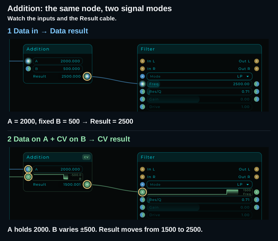
The CV result can continue through other hybrid nodes, such as Multiply → Map → Filter Freq. Those stream-capable stages follow the incoming CV automatically. A Data-only destination cannot directly consume that stream: use CV To Data if you need Data updates there.
Try it: a knob sets the centre, an LFO adds movement
Keep Saw → Filter → Volume → Audio Out from the previous example. Add Addition and use separate inputs for the two controls:
- Set Brightness to Min 1000, Max 4000 and Value 2000. Its values represent the centre frequency in Hz.
- Set the LFO to Free (Hz), Sine, Freq 0.5, Min −500 and Max 500. This time it produces an offset in Hz, rather than the entire cutoff value.
- Remove the direct control cable into Filter Freq, then make these connections:
| From | To | Job |
|---|---|---|
| Brightness Out | Addition A | Set the centre frequency with Data |
| LFO Out | Addition B | Add continuous movement with CV |
| Addition Result | Filter Freq | Send the combined cutoff as CV |
The download includes the complete sound path. It makes a continuous tone; start with your listening volume low and set Volume Gain = 0 to silence it.
Listen and try three changes:
- At Brightness 2000, the cutoff sweeps from 1500 to 2500 Hz.
- Turn Brightness to 3000: the sweep moves to 2500–3500 Hz. The knob moves the centre without stopping the LFO.
- Return Brightness to 2000, then change LFO Min/Max to −250 / +250: the sweep narrows to 1750–2250 Hz.
Addition adds numbers; it does not know which units they represent. Here, both inputs are in Hz. Keep the result in a useful cutoff range. Use Multiply to adjust modulation depth, Map to translate a range, or Clamp to impose limits when building a larger patch.
Two sources on one input behave differently
Separate inputs combine through the node's operation. Two cables on the same input do not automatically create a knob-plus-LFO offset.
If you connect the knob and the LFO directly to the same Filter Freq input, CV takes control:
| Situation | What happens |
|---|---|
| A Data cable is already present, then CV arrives at that input | The Data cable can remain but is suspended while CV controls the input |
| You try to add Data to an input already receiving CV | The new Data connection is refused |
| Data feeds Addition A and CV feeds Addition B | Both are used: Addition holds A and adds each CV value from B |
Suspension can also happen downstream: if a hybrid node's result changes from Data to CV, an existing cable from that result to a Data-only input can remain but stop delivering values. Use a compatible destination or an explicit converter.
Return to manual control
For the Addition example, disconnect LFO Out → Addition B, set B = 0, and turn Brightness again. With no CV source feeding Addition, its Result returns to Data; the existing cable to Filter Freq can stay.
Setting the LFO's speed or depth to zero is different from disconnecting it. A connected LFO still supplies a CV stream even when its value is constant. Remove that CV connection when you want the input to return to Data control.
Remove or correct a connection
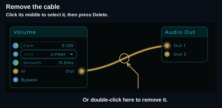
- Remove one cable: click its middle to select it, then press Delete, or double-click the cable to remove it immediately.
- Use the cable's own menu: right-click a cable for Delete Cable, Go to the node at either end, or New Cable from / New Cable to either end.
- Undo a mistake: use Ctrl/Cmd + Z.
- Choose a different destination: remove the wrong cable, then draw it to the correct input. This is the easiest method while learning.
One output, several destinations
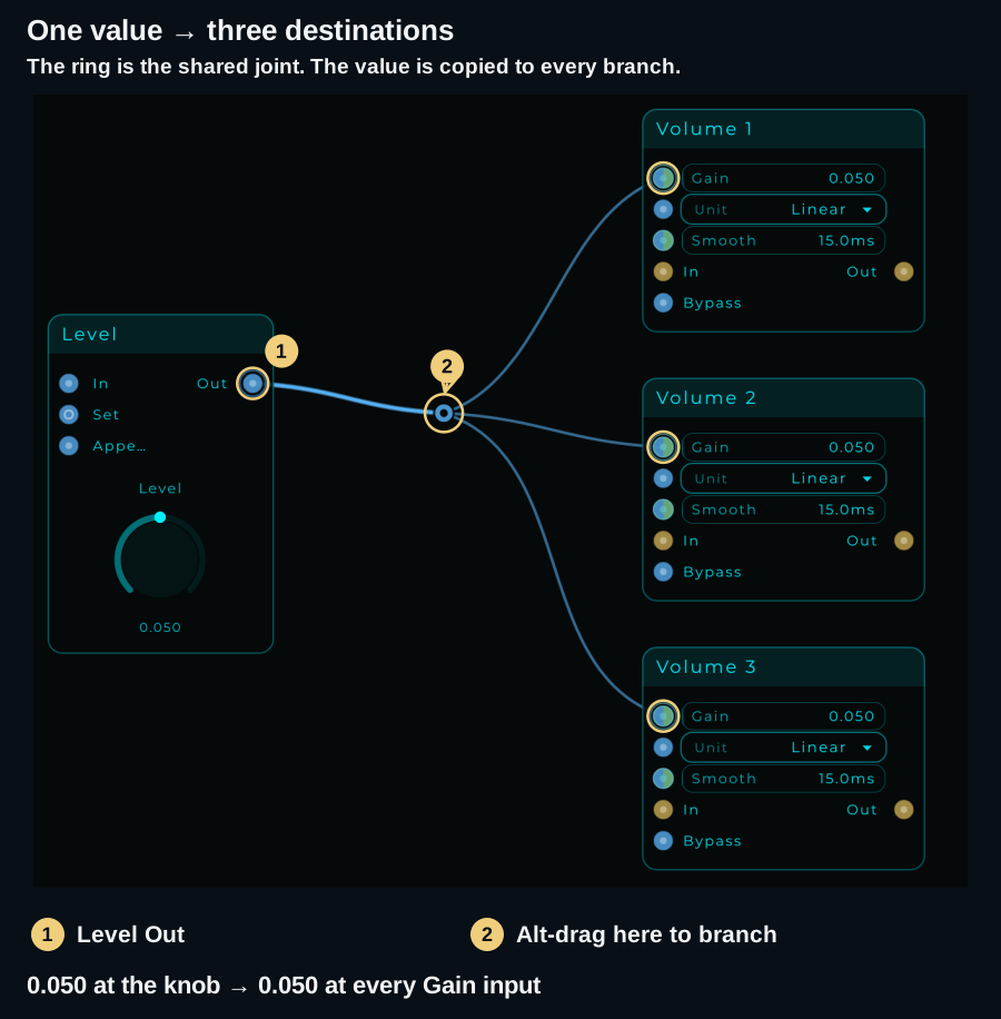
You can draw separate cables from the same output, as in the stereo example above. Joints let you route those cables through a shared point so the graph is easier to follow.
- Connect Level Out → Volume 1 Gain.
- Alt-click the cable to add a joint. Drag the joint to place the bend.
- Hold Alt and drag from that joint to Volume 2 Gain. Repeat for Volume 3 Gain.
- Turn Level. All three Gain values should follow it.
Download: one knob, three levels
This is a control-only exercise: it contains the knob and three Volume nodes, with no sound source or Audio Out. Turn Level and watch the three Gain values. Its range is 0–0.10, and each Volume uses Linear units.
Editing joints and branches
| Action | What to do |
|---|---|
| Add a bend | Alt-click a cable, then drag the joint |
| Remove a joint | Alt-click or double-click the joint; the connection remains |
| Branch from a joint | Hold Alt and drag from the joint to another input |
| Branch from a cable | Hold Alt and drag from the cable; a joint is created when the new branch connects |
| Move several joints together | Shift-click each joint to pick it, or drag a selection box round them, then drag one of them |
| Move joints with their nodes | Select the nodes and drag: the joints of the cables between them go along, and so do the picked joints |
| Straighten cables | Select the nodes or the cables and press Q (Edit > Arrange > Straighten Cables). A cable without joints is straightened by moving the node it goes into; a single selected node lines up with the node that feeds it. Joints that are nearly level take the height of their neighbour. With nothing selected, only joints are levelled |
| Remove just one branch | Select or double-click the cable after the split |
| Remove all cables through a shared section | Select that section and press Delete, or double-click it |
A joint has no sides: the cable runs through it the way it is going. Take a cable back round a node, to an input on the left of where it started, and it turns at each joint in a loop instead of doubling back over it.
The shared section is drawn thicker. Moving a shared joint moves the bend for every cable through it. If only one cable remains, the branching ring becomes an ordinary joint. These bends change the layout of the wires, not the signal they carry.
Faster wiring
Once a single cable feels familiar, try these shortcuts:
| You want to… | Gesture | Result |
|---|---|---|
| Connect a stereo pair or several adjacent pins | Hold Ctrl/Cmd while dragging from the first output to the first input | Following pins travel as ghost cables and connect to the following compatible inputs. Unmatched ghosts stay unconnected |
| Send one output to many inputs | Hold Alt as you drop the cable, then click more inputs | The cable stays attached to its source. Release Alt to finish |
| Repeat a group of connections | Hold Ctrl/Cmd + Alt | Each drop places the compatible group |
What can connect?
| Rule | What it means in the graph |
|---|---|
| Output → input | Two outputs or two inputs cannot be joined |
| Compatible signal types | Audio connects to Audio; MIDI to MIDI. Data/CV compatibility also depends on the pin's capabilities and whether it is already receiving CV |
| One output → many inputs | The signal is delivered to every destination |
| Several sources → one input | The graph can accept several compatible sources. Audio and CV streams are summed; MIDI messages are merged. Data messages arrive individually, so multiple controls can overwrite a parameter's value rather than mix it |
| No direct Audio/CV feedback loop | A cable cannot close a loop through the audio/CV path. Use the appropriate Audio Send/Receive or CV Send/Receive pair when you intentionally need feedback; these introduce one block of delay. See Routing |
For predictable control, start with one source per parameter input. Summing several audio signals can raise the level; use Volume controls or a mixer when combining sound sources.
Front Panel patch cables have different rules. A cable between Jack Out and Jack In is handled by its sockets, and a Jack In accepts one cable. The graph's cable-middle gestures and multiple-source behaviour do not describe those sockets. See Patch Cables.
When you need a converter
Changing a cable's colour does not convert its signal. Use a node that translates the information you need:
| From → to | Converter | Why you might use it |
|---|---|---|
| MIDI → CV | MIDI To CV | Extract note pitch and gate to control a synth |
| MIDI → Data | MIDI To Data | Read note or controller messages as values/events |
| CV → Data | CV To Data | Turn a stream into updates for a Data-only destination |
| Audio → Data | Audio To Data | Read audio-derived values in the Data graph |
| Audio → CV | Audio To CV | Use an audio signal in a CV modulation path |
| CV → Audio | CV To Audio | Route a CV signal into an audio-processing path |
See Converters for the available outputs and settings. Converting a signal type and scaling its range are separate jobs: use Map when the values need a different range.
If a cable does not do what you expect
| What you notice | What to check |
|---|---|
| The cable will not connect | Check output → input, the pin names and compatible types. A CV source cannot directly feed a Data-only input |
| The knob stopped controlling the filter | A CV stream may be controlling that input. Disconnect the CV cable to return to Data control |
| The filter stays very dark | Check the control's range. For this example, send hundreds or thousands of Hz, rather than 0–1 |
| Sound comes from only one speaker | Feed both Out 1 and Out 2 on Audio Out for this mono example |
| Several cables disappeared at once | You may have deleted the shared section before a split. Undo, then select only the branch after it |
| A Jack In replaces its old cable | That is a Front Panel patch-cable rule. See Patch Cables |
| There is still no sound | Follow the gold path to Audio Out, check Volume, then use the first-patch checks |
Pin colours in the Default theme
Audio is gold (#D8B65A), Data blue (#5CB8FF), CV mint green (#82DCA0), and MIDI red (#FF4D6D). Hybrid pins combine the Data and CV colours. You can customise them in Settings → Appearance.
Continue with Working with Nodes for node controls, The Front Panel to build a control surface, or MIDI to move from a continuous tone to notes.