
Appearance
Analysis
Analysis nodes let you see what is going on inside your patch. Drop a waveform display, a frequency view, or a level meter onto the graph (or onto the front panel) to watch a signal live, or use the Print node to list the Data messages coming in while you track down a problem. These nodes only look at the signal, they never change how it sounds, and the visual ones can be restyled and placed on the front panel for live monitoring.
Oscilloscope
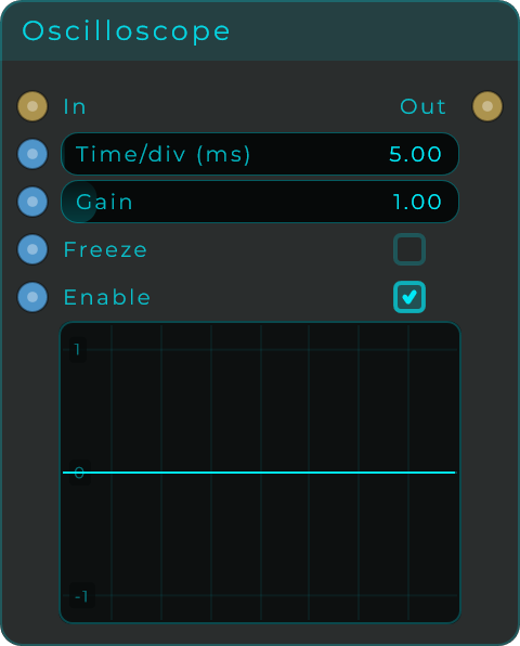
Draws the shape of an audio signal as it happens, so at a glance you can spot a signal sitting off-centre, distortion from a level that is too hot, a lopsided waveform, and how the shape changes over time. The drawing adjusts to how far you zoom (a filled-in outline when zoomed out, smooth detailed waves when zoomed in), and the body can be placed on the front panel.
| Parameter | Range | Default | Description |
|---|---|---|---|
| Time/div (ms) | 0.05 to 500 ms | 5 ms | Milliseconds per division. There are 8 divisions across the display, so this sets the horizontal time scale. |
| Gain | 0.1 to 10 | 1.0 | Visual gain applied to the trace. Scales the waveform vertically without changing the audio. |
| Freeze | on / off | off | Freezes the current display so you can study it. |
| Enable | on / off | on | Turns signal capture on or off. |
Inputs: In (audio); plus Data input pins for Time/div, Gain, Freeze, Enable, and an Appearance pin that accepts a JSON style object.
Outputs: Out (audio, pass-through of the input).
CV Scope
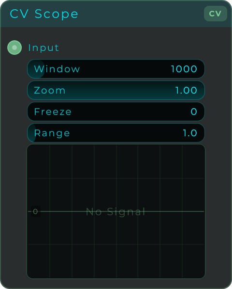
A display for CV and Data signals, so you can watch how a control or modulation value moves over time. It listens to a full CV stream at its input and draws its recent history, and the body is ready to place on the front panel for live monitoring.
| Parameter | Range | Default | Description |
|---|---|---|---|
| Window | 10 to 10,000 ms | 1000 ms | Timebase of the display. Sets how much recent history is shown, in milliseconds. |
| Zoom | 0.1 to 1.0 | 1.0 | Vertical zoom applied to the trace, without changing the signal. |
| Freeze | on / off | off | Freezes the current display so you can study it. |
| Range | 0 to 20 | 1.0 | Vertical range used to map the trace. |
Inputs: In (Data, accepts a full-CV stream).
Outputs: None. The CV Scope only displays the signal.
Pitch Detector
Listens to a monophonic signal and follows its pitch, reporting the same reading four ways so it can drive a synth voice, a tuner display, or both at once. The body is a tuner: the note name, how far off it is in cents, and the frequency in Hz, and it can be placed on the front panel.

| Parameter | Range | Default | Description |
|---|---|---|---|
| Min Freq | 20 to 2,000 Hz | 50 Hz | Lowest note to look for. Keeping it near the instrument's real range makes the tracking steadier. |
| Max Freq | 50 to 8,000 Hz | 2,000 Hz | Highest note to look for. |
| Threshold | 0 to 1 | 0.02 | How loud the input has to be to count as a note rather than silence. |
| Min Confidence | 0 to 1 | 0.5 | The lowest reading on the Confidence output that still counts as a note. Watch that output on the sound you are tracking and set this just below what you see: too high and the Gate never opens, too low and noise reads as a note. |
| Glide | 0 to 500 ms | 20 ms | Smoothing between notes. It works on the note number, so the same time means the same musical distance in any register. |
| Mode | Accurate / Fast | Accurate | Accurate analyses a longer window and reaches lower notes; Fast reacts sooner and loses the bottom of the range. |
| Hold Last Note | on / off | on | Keeps the last reading while the input is silent instead of dropping to zero. Usually what you want when driving an oscillator. |
Inputs: Audio In (audio); plus a hybrid input pin for every parameter above (Min Freq, Max Freq, Threshold, Confidence, Glide, Mode, Hold), each taking either a plain value or a CV stream, and an Appearance pin that accepts a JSON style object.
Outputs: Hz (frequency), Note (MIDI note number with decimals, so a slide stays smooth), Gate (1 while a note is tracked) and Confidence (0 to 1, how periodic the input looked). All four are CV, so each one carries a value and a full-rate signal at once: wire Hz straight into an oscillator's frequency, or into a display, without a converter in between.
Confidence appears twice, and they are two sides of the same number: the Confidence output is the measurement, how periodic the input looked from 0 to 1, and it is drawn as the CONF bar in the tuner. Min Confidence is the bar you set for it: while the measurement stays above it, the Gate is open and the readings are treated as a real note. A clean solo instrument sits high, breath and noise sit low; at the very top of its range nothing passes at all.
Note how Hold Last Note reads against it: when a reading is rejected (too quiet, or below Min Confidence) the Gate closes, but Hz and Note keep the last note they trusted rather than diving to zero, which is what you want when they are driving an oscillator. The tuner says HOLD while it is showing a frozen note, so it is never mistaken for a live one. Turn Hold Last Note off and the outputs fall to zero instead.
Two more things worth knowing. It is monophonic: on a chord it locks onto whatever is most periodic. And it has some latency by nature, because a period has to be heard before it can be measured, so the lowest notes are always the slowest to read (about 43 ms of window in Accurate, 21 ms in Fast, at 48 kHz). The node keeps running even with nothing wired into its input, so its outputs and the tuner are alive from the moment you drop it in.
Analyzer
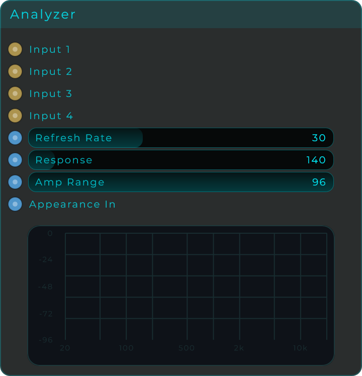
A frequency display with four inputs that shows which pitches make up your sound, drawing each input as its own coloured line. Low notes sit on the left and high notes on the right, while louder content reaches higher up, so you can compare up to four signals side by side on a panel-ready display.
| Parameter | Range | Default | Description |
|---|---|---|---|
| Refresh Rate | 12 to 60 Hz | 30 Hz | How often the display redraws, in frames per second. |
| Response | 10 to 1,500 ms | 140 ms | Smoothing time for the measured spectrum. Higher values look smoother but react more slowly. |
| Amp Range | 48 to 96 dB | 96 dB | Visible amplitude range in dB, measured down from the 0 dBFS top line to the analyzer floor. |
Inputs: Input 1, Input 2, Input 3, Input 4 (audio); plus Data input pins for Refresh Rate, Response, Amp Range, and an Appearance pin that accepts a JSON style object.
Outputs: None. The Analyzer only displays the signal.
Meter
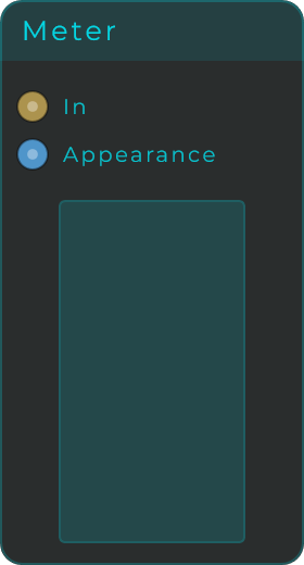
A level meter for keeping an eye on how loud your audio is. It shows the current peak plus a marker that hangs at the loudest recent level, lights up when the signal is too hot (clipping), and is ready to place on the front panel for live performance. You can draw it standing up or lying down, and it can show the current value as a number too.
| Parameter | Range | Default | Description |
|---|---|---|---|
| Floor dB | -96 to -12 dB | -48 dB | Lower dB limit used to map the meter range. |
| Peak Hold (ms) | 0 to 4,000 ms | 900 ms | How long the peak marker stays before it starts to fall. |
| Show Value | on / off | off | Shows the current peak value as text over the meter. |
| Orientation | Vertical / Horizontal | Vertical | Draws the meter vertically or horizontally. On the front panel the widget turns with it, width for height |
| Segment Count | 2 to 96 | 16 | How many segments the Segments fill style splits the lane into. |
| Scale Marks | 0 to 24 dB | 0 (off) | How far apart the marks are, in decibels. A gap, not a count, so a small number draws many marks. |
| Scale Mark Width | 0.5 to 4 | 1 | Thickness of those lines. |
| Scale Mark Colour | colour | follows the border | Colour of the scale marks. |
| Channels | Merged / Stereo | Merged | One lane for the pair, or a lane each. Stereo also splits every output pin into an L and an R. |
| Meter Mode | Peak / RMS | Peak | What the bar itself shows. It does not decide what is measured: Peak and RMS are both worked out every block either way. |
One segment per dB. Set Segment Count to the same number as your Floor and each segment is worth exactly one decibel: 72 segments with a -72 dB floor, 48 with -48, and so on. The ceiling is 96 because that is as far down as the floor goes, so the trick works wherever you set it. (Suggested on the forum by Danny.)
Scale marks. Set Scale Marks to 6 and the meter draws a line every 6 dB, at -6, -12, -18 and so on down to the floor. The number is the gap between marks rather than how many you get, so a small value draws a lot of them: 1 puts a line at every single decibel and fills a short meter, while 24 leaves a single mark. Spacing them in decibels is what keeps them on round values and keeps them put when you change the Floor. They are drawn over the level rather than under it, because a scale you cannot see while the meter is lit is a scale you cannot read when you need it, and they work with any fill style. Leave Scale Mark Colour empty and they follow the border colour.
Peak and RMS at the same time. Meter Mode only chooses what the bar draws. Both measurements are made every block regardless, and both leave the node on their own pins, so one Meter can drive a gate from its peak and a level readout from its RMS without a second Meter in the patch.
What RMS means here. The RMS reading is the average loudness over the last third of a second or so. It rises and falls smoothly where Peak jumps, a steady sine reads 3 dB under its peak as it should, and the number is the same whatever audio buffer size you run. To steer something from a level (an auto gain, a ducker) rather than read it, use Sig To RMS: the same measurement as a signal, with a Window you choose.
Inputs: In (audio); plus an Appearance pin that accepts a JSON style object to restyle the meter externally.
Outputs: Level, Peak, RMS (Data, in dB). Level follows Meter Mode; Peak and RMS are always themselves. Silence reads as Floor dB rather than minus infinity, so the cable always carries a number you can do arithmetic on. With Channels set to Stereo each of the three becomes a pair, Level L and Level R and so on.
Stereo Image
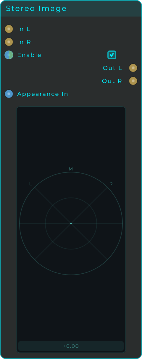
A stereo image and phase display. It draws a vectorscope so you can see the width and phase of a stereo signal at a glance: a vertical line means the signal is mono, a round cloud means it is wide, and a horizontal line means the two sides are out of phase. A meter underneath reads the phase correlation from +1 (mono) through 0 (wide) down to -1 (out of phase), with the value shown as a number. The audio passes straight through, so you can drop it inline on a stereo bus, and the body can be restyled and placed on the front panel.
| Parameter | Range | Default | Description |
|---|---|---|---|
| Enable | on / off | on | Turns signal capture on or off. |
| Persistence | 0 to 1 | 0.5 | How long the scatter trail fades. Higher leaves a longer trail. |
| Dot Size | 0.5 to 4 | 1.6 | Size of the dots in the scatter. |
| Connect Dots | on / off | off | Joins the scatter samples with a line, so the trace reads as one continuous shape instead of a spray of dots. |
| Show Phase Bar | on / off | on | Shows or hides the phase correlation meter under the scope. |
| Value Size | 6 to 28 | 10 | Text size of the correlation value. |
| Label Size | 6 to 28 | 9 | Text size of the L, R and M axis labels. |
Inputs: In L, In R (audio); plus a Data input pin for Enable, and an Appearance pin that accepts a JSON style object.
Outputs: Out L, Out R (audio, pass-through of the input).
Print
A simple running log for tracking down problems. Connect any Data output to its input and every message that arrives is printed as a new line, so you can see exactly which values and events are moving through your patch. The recent lines are kept with the node and you can scroll back through the list to inspect them.
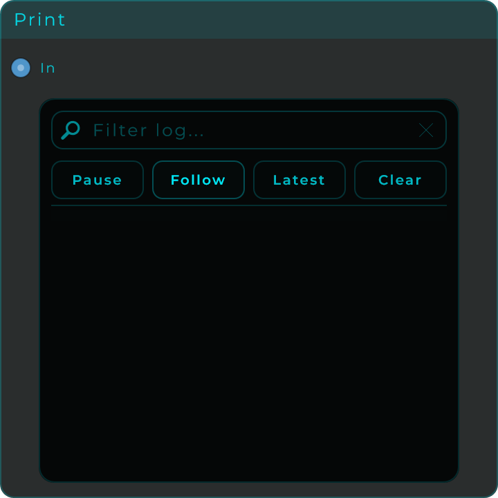
Inputs: In (Data). Accepts any message type: events, floats, integers, booleans, and text. Each message prints one new line.
Outputs: None.
Reactor Core
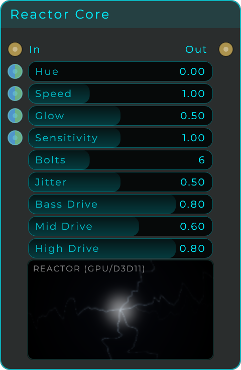
A visualiser rendered on the graphics card: a glowing plasma core that fires lightning bolts out toward the edges, driven by your sound. The low end of the signal gives the bolts their power and thickness, the mids move them around, and the highs add flicker and sparks. Sensitivity sets how strongly the sound drives it all, and the Bass, Mid and High Drive controls balance the three. The audio passes through unchanged, so you can drop it anywhere in a signal chain as pure eye candy for a performance.
| Parameter | Range | Default | Description |
|---|---|---|---|
| Hue | 0 to 1 | 0 | Colour of the core and its bolts. |
| Speed | 0 to 3 | 1 | How fast the bolts flicker and travel. |
| Glow | 0 to 1 | 0.5 | Thickness and glow of the bolts. |
| Sensitivity | 0 to 2 | 1 | Overall amount the audio drives the visual. |
| Bolts | 1 to 16 | 6 | How many bolts fire. |
| Jitter | 0 to 1 | 0.5 | How jagged the bolts are. |
| Bass Drive | 0 to 1 | 0.8 | How much the low end powers and thickens the bolts. |
| Mid Drive | 0 to 1 | 0.6 | How much the mids move the bolts around. |
| High Drive | 0 to 1 | 0.8 | How much the highs add flicker and sparks. |
Inputs: In (audio); plus modulation inputs for Hue, Speed, Glow and Sensitivity, each accepting a value or a CV signal.
Outputs: Out (audio, pass-through of the input).
Mandelbulb
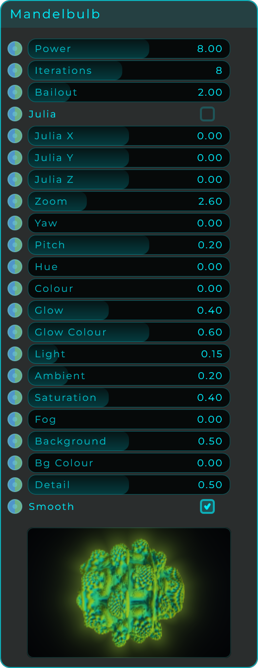
A three-dimensional fractal rendered on the graphics card, ready to explore and animate. Every control is an input you can modulate with a value or a CV signal: shape the fractal with Power, Iterations, Bailout and the Julia switch with its X, Y and Z; move the view with Zoom, Yaw and Pitch; and set the look with Hue, Colour, Glow, Glow Colour, Light, Ambient, Saturation, Fog, Background, Bg Colour, Detail and Smooth. It makes no sound and never touches the audio, a purely visual node, and it can be placed on the front panel. There is no automatic rotation, so wire a slow LFO into Yaw to make it spin.
| Parameter | Range | Default | Description |
|---|---|---|---|
| Power | 2 to 12 | 8 | The strength of the folding that shapes the fractal. Changes the whole form. |
| Iterations | 1 to 16 | 8 | How many times the shape is refined. Higher is more intricate. |
| Bailout | 1.2 to 5 | 2 | How far the calculation is allowed to run. Alters the surface. |
| Julia | on / off | off | Switches to the Julia variant of the fractal. |
| Julia X / Y / Z | -2 to 2 | 0 | The seed point of the Julia variant. |
| Zoom | 1.2 to 6 | 2.6 | Distance from the fractal. |
| Yaw / Pitch | 0 to 1 / -1 to 1 | 0 / 0.2 | Rotation around the fractal and the tilt of the view. |
| Hue / Colour | 0 to 1 | 0 / 0 | Base colour and how the colours spread across the surface. |
| Glow / Glow Colour | 0 to 1 | 0.4 / 0.6 | Edge glow amount and its colour. |
| Light / Ambient | 0 to 1 | 0.15 / 0.2 | Strength of the main light and of the overall base light. |
| Saturation | 0 to 1 | 0.4 | Colour intensity. |
| Fog | 0 to 1 | 0 | Fades the fractal into the background with distance. |
| Background / Bg Colour | 0 to 1 | 0.5 / 0 | Background brightness and its colour. |
| Detail | 0 to 1 | 0.5 | Rendering fineness. |
| Smooth | on / off | on | Smooths the rendered surface. |
Inputs: one modulation input per control listed above, each accepting a value or a CV signal.
Outputs: None. The Mandelbulb only draws itself.